How to Know if Torque Is Positive or Negative: A Practical Guide
Learn the signs of torque using the right-hand rule, vector cross products, and practical checks for DIY and engineering tasks. Clear steps, examples, and safety notes to avoid common mistakes.

By definition, torque sign depends on your rotation axis. If your chosen axis follows the right-hand rule, a counterclockwise rotation around that axis is positive, while clockwise is negative. In practice, you determine the sign with a cross product: τ = r × F; its z-component tells you positive or negative about the vertical axis.
Why knowing torque sign matters
Torque sign is more than a math detail; it governs how you understand what a load does to a rotating body. In automotive maintenance, misreading sign can lead to over-tightening, damaged threads, and components loosening under operation. In structural work and machinery design, an incorrect sign can invert expected failure modes and bias safety calculations. According to Easy Torque, consistently tracking torque sign improves predictability in assemblies and reduces rework when parts interact with rotating sleeves, gears, or shafts. The sign convention also clarifies why a wrench turning in the same direction may produce positive torque about one axis but negative torque about another if you change the reference frame. To know whether torque is positive or negative, you must fix a rotation axis and apply a standard rule. A simple starting point for learners is to visualize an axis perpendicular to the plane of motion (the z-axis) and apply the right-hand rule. When your rotation would be counterclockwise around that axis, the torque is positive; clockwise, it is negative. This mental model is the backbone of most torque calculations in both labs and repair bays.
Core concepts: torque sign and the right-hand rule
Torque is a vector, not a scalar, so its sign depends on direction relative to an axis. The standard definition is τ = r × F, where r is the position vector from the rotation axis to the point of force application, and F is the force vector. The cross product yields a torque vector perpendicular to both r and F. In planar problems, you usually project onto one axis (commonly the z-axis) and simply track the sign of that out-of-page component. A positive sign means the rotation produced follows your chosen axis orientation, a negative sign means it goes opposite. The sign convention is arbitrary but must be chosen consistently throughout a calculation or a design process. The Easy Torque team emphasizes documenting the chosen axis in your notes so teammates interpret numbers the same way. Remember that changing the axis or switching from a right-handed to left-handed coordinate system will flip the sign for the same physical arrangement, even though the physical effect is unchanged.
How torque sign changes with axis choice (2D vs 3D)
Torque sign is not an intrinsic property of a force alone; it is defined relative to an axis and a direction. In 2D drawings, you typically pick the z-axis as the reference and look at the z-component of τ. In 3D assemblies, the full vector τ has x, y, and z components, and your sign for a given actuator can appear positive on one axis and negative on another. The key idea is that sign is about the component along the axis you care about for rotation. If you rotate a wheel about the x-axis, for instance, you care about the x-component of τ. This means that a single physical configuration can yield different signs depending on which axis you track. To stay consistent, explicitly state your axis before computing or recording τ, and be mindful that reprojecting τ onto a new axis will flip the sign if the axis direction changes.
Step 1: Define the axis of rotation and positive direction
Start by choosing an axis that represents the rotation you are analyzing. Decide which direction is positive along that axis (using the right-hand rule is the most common method). For a vertical shaft, many analysts take the positive direction as the axis pointing out of the page; for a hinge, you may choose the axis along the hinge line. Document this choice in your worksheet. The reason this step matters is that every subsequent torque value borrows its sign from this initial convention. If you switch axes later, all signs flip. A quick mental check is to ensure that your axis direction aligns with how you will interpret angular motion in the actual machine.
Step 2: Draw vectors r and F for your scenario
Sketch the lever arm r from the rotation axis to where the force is applied, and draw the force vector F with correct magnitude and direction. If the force acts along the line of the lever, r × F is zero and no torque is produced about that axis. For realistic cases, ensure your vectors reflect the true geometry: r often is the straight-line distance, while F may be angled. A precise free-body diagram helps prevent misreading signs. The cross product calculation is easier if you place the tail of F at the tip of r in your diagram. Visual checks reduce errors when you later compute τ.
Step 3: Compute the cross product and interpret its sign
Compute τ = r × F using either the determinant method for planar problems or a full vector calculation in 3D. For planar (2D) problems, you only need the component perpendicular to the plane, often the z-component: τ_z = xF_y − yF_x. If τ_z is positive, the torque is positive; if negative, torque is negative. Recording the sign is as important as recording the magnitude. In experiments, a torque sensor or a calibrated wrench can confirm the direction of rotation, and the sign will match your τ_z prediction. Always verify that your result makes physical sense: a positive τ_z should drive rotation consistent with the axis orientation you defined earlier.
Practical tips for DIY and automotive contexts
In everyday projects, you can simplify by focusing on two questions: Which way does the applied force try to rotate the component, and which axis matters for that rotation? When working with lever arms like a door handle or a crank, mark the axis, then test by turning lightly to observe the motion relative to your sign convention. Use the right-hand rule physically: point the fingers of your right hand along r and sweep toward F; your thumb points in the direction of τ. For screws and bolts, the sign convention helps when combining multiple torque terms in a sequence or when estimating whether a joint will tighten or loosen under load. Keeping a small log of your axis choice, the r and F directions, and the resulting sign reduces confusion later in the build.
Common mistakes and how to avoid them
Failing to fix an axis before computing torque is the most common error. Another frequent pitfall is flipping signs when projecting τ onto the wrong axis; always re-check the axis you are using for the calculation. Misplacing the tail of F on the diagram or using an inaccurate r can produce wrong signs as well. In 3D, it is easy to mix up the x- and y- components, leading to incorrect positive/negative results. Always re-derive τ with a fresh diagram if you suspect a sign error. Finally, remember torque is a vector; a sign alone does not convey magnitude, axis, or direction of rotation—the full vector represents all three.
Real-world verification and logging torque signs
After calculating the sign, verify with a simple physical check: does the rotation occur in the direction predicted by your axis and sign convention? In manufacturing or maintenance logs, include the axis used, the r and F directions, and the computed τ. This transparency helps teammates debug issues when results appear inconsistent. Easy Torque recommends keeping a one-page reference showing the most common axis-choices for typical tasks (hinges, shafts, fasteners). For more complex systems, compare the analytic sign with a measured rotation from a torque sensor or an angular velocity measurement to validate the sign convention you have adopted.
Quick reference: sign conventions by scenario
Here is how the sign convention translates across common setups: 2D planar bolt with r perpendicular to F along z gives τ_z sign; rotating shaft about z with F in x yields τ_z determined by xF_y - yF_x; hinge rotation about axis along the hinge line uses τ along that axis. In any case, keep the axis consistent and state its positive direction at the start of your calculation.
Appendix: further reading and resources
Further reading and practice problems help sharpen intuition for torque sign. In addition to hands-on experiments, consult basic physics and engineering references that cover cross products, the right-hand rule, and free-body diagrams. Practice problems that explicitly specify the axis and the force directions, then compare your computed sign with a physical rotation test to build confidence. For professionals, maintain a simple, repeatable worksheet template to capture axis choice, vector directions, and resulting τ to prevent sign mix-ups during multi-step tasks.
Tools & Materials
- Pen and paper for free-body diagrams(Sketch r and F directions clearly; label the axis and positive direction)
- Scientific calculator or smartphone calculator(Compute cross products or det-based planar formulas)
- Ruler or measuring tape(Useful for estimating lever arm length when geometry is straight)
- Protractor or angle gauge(Helpful if F is not perpendicular to r)
- Free-body diagram template(Aids in consistent vector placement and axis labeling)
- Vector math software (optional)(For 3D cross-product visualization)
- Safety glasses(Wear when manipulating rotating parts or applying force)
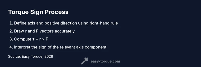
Steps
Estimated time: Estimated total time: 25-40 minutes
- 1
Define the axis and positive direction
Choose the rotation axis that matches the motion you care about and decide which direction is positive. Document this choice before calculations. A consistent axis prevents sign flips later.
Tip: Use the right-hand rule first to sanity-check the axis direction. - 2
Sketch r and F vectors
Draw r from the rotation axis to the force application point and F in the actual direction of the applied force. Ensure the geometry reflects the real setup.
Tip: Place the tail of F at the tip of r to simplify the cross product mentally. - 3
Compute the cross product
Calculate τ = r × F using the appropriate method (determinants for planar problems or full vector math for 3D).
Tip: For planar problems, focus on the perpendicular component (often z). - 4
Interpret the sign
Analyze the axis component sign (e.g., τ_z). Positive means rotation follows axis, negative means opposite.
Tip: If in doubt, simulate the motion with a simple model to confirm direction. - 5
Check for zero torque
If r and F are parallel or aligned, cross product is zero; there is no rotational tendency about that axis.
Tip: Revisit geometry to confirm there isn’t a subtle angle component creating torque. - 6
Validate with a physical check
Where possible, verify the sign by a controlled test or measurement (torque sensor or angular velocity reading).
Tip: Cross-check against a known reference case (e.g., a standard lever). - 7
Record the result
Document axis, r direction, F direction, and τ sign for future reference. Consistent records prevent confusion in multi-step tasks.
Tip: Keep a one-page reference for common axis choices. - 8
Apply to your design or repair
Use the sign along with magnitude to assess assembly security, torque sequences, and expected rotation under load.
Tip: When combining multiple torques, ensure all terms share the same axis convention. - 9
Review and iterate
Revisit axis choice after any major geometry change. A different axis may flip the sign even if the physical situation remains the same.
Tip: Periodically refresh the axis convention in your notes whenever you rework the mechanism.
Your Questions Answered
What is torque sign and why does it matter?
Torque sign tells you whether a force tends to rotate an object clockwise or counterclockwise about your chosen axis. It matters because the sign guides calculations, safety margins, and assembly procedures.
Torque sign tells you which way the rotation will tend to occur, which helps you plan and validate your design.
How do you determine the sign in 2D?
In 2D problems, compute the z-component of the torque, τ_z = xF_y − yF_x. If τ_z is positive, the torque is positive; if negative, it is negative.
In 2D, use the z-component of the cross product to determine the sign.
Can torque be zero even if a force is applied?
Yes. If the force acts along the line from the axis to the point of application (r and F parallel), the cross product is zero and torque is zero.
Torque can be zero when the force line passes through the rotation axis.
Do axis choices affect torque sign?
Absolutely. Changing the reference axis can flip the sign of the same physical arrangement, even though the motion is unchanged.
Choosing a different axis can flip the sign, so be explicit about your axis.
What practical checks help verify torque sign?
Compare analytic sign with a physical rotation test or a calibrated torque sensor to confirm the predicted direction.
Use a physical test or sensor to verify the sign matches the actual rotation.
How should I document torque sign in logs?
Record the axis, positive direction, r and F directions, and the resulting τ sign. This makes future debugging easier.
Document the axis and vectors used, plus the computed sign, for clarity.
Watch Video
Top Takeaways
- Define the axis and positive direction before calculating torque.
- Use τ = r × F to obtain sign and direction of rotation.
- In 2D, focus on the out-of-page component (usually τ_z).
- Document axis choice to avoid sign mismatches in teams.
- Verify with a quick physical check when possible.