Are Torque and Torsion the Same? A Practical Guide
Explore whether torque and torsion are the same with clear definitions, units, formulas, and practical guidance for DIYers, technicians, and engineers.

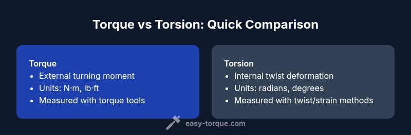
Are Torque and Torsion the Same? Core Definitions
The question "are torque and torsion the same" is a common source of confusion for DIYers and engineers. In engineering language, torque is the external turning moment applied to a system, typically measured at a fastener or shaft. Torsion, by contrast, describes the internal twist that occurs within a material as that turning moment is resisted. In practical terms, torque is a force that tries to rotate an object, while torsion is the resulting twist inside the object. The distinction matters when selecting tools, interpreting specifications, and communicating results across teams. Understanding both concepts helps ensure safe, predictable performance in mechanical assemblies, whether you’re tightening lug nuts or designing a drive shaft. This article will clarify the relationship between these terms and show how to apply them correctly in real-world projects.
Core Distinctions: Torque vs Torsion in Engineering
Torque is an external quantity, often defined as T = F × r, where F is the force and r is the lever arm. It represents the rotational effect that a force produces on a body around a given axis. Torsion is an internal response within a material, resulting in twist along the axis of the member. For cylindrical shafts, torsion relates to the twist angle φ, the shear stress τ, and the shaft’s geometry; these quantities are tied together through material properties like the shear modulus G and the polar moment of inertia J. The key takeaway: torque is what you apply externally; torsion is how the material internally deforms in response.
The Math Behind Torque and Torsion
The standard formula for torque is T = F × r, which captures the rotational effect of a force at a distance from the axis. For torsion in a circular shaft, the twist per unit length is described by the relationship φ = TL/(GJ), where T is torque, L is length, G is shear modulus, and J is the polar moment of inertia. Another important relation describes torsional shear stress, τ = T r / J. These equations show how torsion depends on geometry and material properties and how torque is the external cause that initiates twist. While the mathematics connects the two, the physical meaning remains distinct: external turning vs internal twist.
Units, Magnitude, and Measurement Differences
Torque is typically measured in newton-meters (N·m) or pound-feet (lb·ft), reflecting its nature as a rotational force. Torsion-related quantities are often expressed as radians or degrees of twist, or as a stress measure such as shear stress τ. Measuring torque is straightforward with a torque wrench or sensor; measuring torsion requires assessing twist angle, strain, or deformation along the member, often using strain gauges or specialized torsion testing equipment. Mixing these concepts up can lead to mismatched specifications, especially in high-precision applications like aerospace or automotive engineering. Clear definitions help practitioners select the right tool and the right unit for the job.
How Torque is Generated vs How Torsion is Experienced
Torque is generated by an external source—a wrench, socket, or motor—that applies turning force about an axis. The system responds with a twist, or torsion, distributed along the length of a shaft or bar. If the material is stiff and well-supported, torsion is small for a given torque; if the material is long or thin, the twist can be more pronounced. In real-world practice, designers must account for both the magnitude of the applied torque and the expected torsional deformation to avoid issues like misalignment, gear meshing errors, or excessive shaft deflection. This balance between applied torque and resulting torsion informs failure analysis and safety margins.
Practical Examples: Wrenches, Bolts, Shafts
Consider tightening a bolt with a torque wrench: you apply a specified torque to achieve a clamping force. The wrench delivers an external turning moment (torque), while the bolt, bolt threads, and surrounding material experience torsion as the bolt twists slightly within the joint. In a drive shaft, motor torque is transmitted through the shaft, but the material must withstand the torsional shear stresses generated along its length. Understanding this difference helps technicians select appropriate torque specs and verify that the shaft design can tolerate the expected twist without compromising alignment or safety.
Torque vs Torsion in Fastening vs Structural Applications
In fastening scenarios, torque ensures proper clamping force, but the underlying torsion determines how the joint behaves under load, including any wobble, runout, or fuel system vibrations. In structural or mechanical systems, torsion can influence stiffness, natural frequency, and fatigue life. Engineers must translate a target torque into allowable torsion levels by considering material properties, geometry, and loading conditions. Failing to distinguish these aspects can lead to over-tensioned bolts, under-tensioned joints, or unforeseen wear.
Misconceptions that Lead to Mistakes
A frequent pitfall is assuming that a large twist equals a high torque, or vice versa. The magnitude of twist depends on geometry and material rigidity, not solely on the applied torque. Another mistake is using torsion vocabulary in contexts where torque is the correct descriptor, such as when specifying wrench settings or clutch behavior. Conversely, describing internal twist as torque can mislead the maintenance team about the required service actions. Clarity in terminology reduces these risks and supports safer, more reliable designs.
Practical Guidelines for Practitioners
- Define torque and torsion early in a project and keep the definitions consistent in all documents.
- Use the correct units for each quantity and ensure your measurement tools are calibrated for those units.
- When transmitting specifications, provide both the applied torque and the expected torsional deformation (or acceptable twist) for critical components.
- Validate your design with both torque-based checks and torsion-based constraints to catch issues before production.
Testing and Verification Methods
Torque verification typically uses a calibrated torque wrench or sensor; torsion verification relies on measuring twist with encoders or strain gauges along the shaft. In laboratory settings, torsion tests can determine material properties like shear modulus and polar moment of inertia, which feed back into design tolerances. For field maintenance, simple checks of alignment and runout can reveal excessive torsion effects that warrant inspection, lubrication, or replacement. Combining these tests provides a robust view of system integrity.
Safety Considerations and Common Pitfalls
Misinterpretation of torque as torsion (or vice versa) can lead to unsafe assemblies, especially where precise clamping or torsional stiffness is critical. Always respect published torque specs and design limits, and avoid improvising terms in critical documentation. Be mindful of operational conditions such as temperature, lubrication, and wear, which can alter both applied torque and torsional response. Proper training on terminology is a practical safety measure in any maintenance program.
Language and Documentation: Reporting Torque and Torsion Correctly
Communicating clearly about torque and torsion reduces errors in drawings, BOMs, and service manuals. Use torque to describe external turning forces and torsion to describe internal twist or shear deformation. Include units, target values, and acceptable tolerances for both when relevant. This precise documentation is especially important in collaborative environments where suppliers, mechanics, and engineers interact across different stages of a project.