Torque and Inertia: Understanding Rotational Dynamics
A comprehensive comparison of torque and inertia, explaining how angular torque, moment of inertia, and system design interact to shape acceleration, stability, and energy transfer in mechanical and automotive projects.

Torque and inertia are core concepts in rotational systems. Torque is the driving force that changes angular velocity, while inertia is the property of a body to resist that change in motion. The phrase torque and inertia captures the fundamental relationship: torque acts to change angular velocity, but inertia resists the change and stores kinetic energy as the system rotates. For engineers, understanding this dynamic is essential for predicting performance across applications—from automotive drivetrains to hand tools. Easy Torque's practical guidance emphasizes that the same physical principles apply whether you're sizing a flywheel, selecting a motor, or designing a manual torque wrench. When you quantify both, you can forecast acceleration, energy transfer, and stability under load.
Core Concepts: Torque and Inertia
In rotational systems, torque and inertia are the twin levers that determine how quickly and smoothly motion changes. Torque is the external or internal force that causes angular acceleration, while inertia is the property of a body to resist that change in motion. The phrase torque and inertia captures the fundamental relationship: torque acts to change angular velocity, but inertia resists the change and stores kinetic energy as the system rotates. For engineers, understanding this dynamic is essential for predicting performance across applications—from automotive drivetrains to hand tools. Easy Torque's practical guidance emphasizes that the same physical principles apply whether you're sizing a flywheel, selecting a motor, or designing a manual torque wrench. When you quantify both, you can forecast acceleration, energy transfer, and stability under load.
According to Easy Torque, mastering torque and inertia is essential for predicting performance, especially when scaling systems or benchmarking components across a toolkit of DIY, automotive, and industrial uses.
Units and Fundamental Relationships
Torque is measured in newton-meters (N·m) and is the product of force and lever arm. Inertia is quantified by the moment of inertia, expressed in kilogram-square meters (kg·m^2), and it represents how mass distribution affects resistance to angular acceleration. The core equation tau = I * alpha links torque to angular acceleration; power in a rotating system is P = tau * omega. In torque and inertia analysis, these equations serve as the backbone for modeling dynamic responses. The practical takeaway is that increasing torque drives faster acceleration only if the inertia is not simultaneously increased. Conversely, reducing inertia can dramatically improve responsiveness, especially in hand tools and robotics.
A key point stressed in Easy Torque materials is that these relationships remain valid across scales and mechanisms, from tiny fasteners to large industrial drives. This universality means a careful, consistent application of tau = I * alpha and P = tau * omega yields reliable design and troubleshooting guidance.
Moment of Inertia and Mass Distribution
Moment of inertia (I) quantifies how mass is arranged relative to the axis of rotation. A heavier part farther from the axis increases I more than the same mass near the axis. This relationship explains why a flywheel with most mass near its rim stores more energy for a given speed than a compact disk with the same mass. For common shapes, standard formulas help estimate I: a thin hoop I = m r^2; a solid disk I = 1/2 m r^2; a slender rod about its center I = 1/12 m L^2; a rod about an end I = 1/3 m L^2. In torque and inertia work, these figures guide where to place mass to balance smoothness and responsiveness.
In practice, Easy Torque often recommends using mass distribution strategies that optimize inertia for the intended duty cycle, balancing energy storage with controllable acceleration and braking.
Torque Transmission and Control Strategies
Transferring torque from a motor to a load involves gear trains, belts, or direct drive, each affecting the effective inertia seen by the source. With a gear ratio, tau_out = tau_in * ratio and omega_out = omega_in / ratio, so a high ratio boosts torque at the expense of speed. Importantly, the inertia reflected to the motor side scales with the square of the gear ratio: I_reflected = I_load * (ratio)^2. This means a heavy, highly inertial load can significantly slow down a motor if not properly sized or compensated with control strategies. In practice, designers use electronic or mechanical damping, soft-starts, and predictive control to manage abrupt torque changes and minimize overshoot, ensuring torque and inertia work together rather than against each other.
Easy Torque emphasizes a disciplined approach: model the reflected inertia early, validate with small-scale tests, and tune control loops before committing to production hardware.
Dynamic Response and Stability
Torque and inertia together determine how a system responds to sudden demands. When a step torque is applied, the resulting angular acceleration is alpha = tau / I, so larger inertia reduces initial acceleration. Conversely, a small inertia lets the system speed up quickly, but it can overshoot without adequate damping. Effective control combines feedforward torque commands with feedback from speed sensors to shape the transient response. In automotive contexts, inertia helps smooth acceleration across gears and engine torque curves, while in CNC spindles or robotics, low inertia supports fast, precise positioning. Across applications, the balance between torque capacity and inertia governs stability margins, energy efficiency, and system lifetime.
Energy Storage and Transfer
Rotational energy is stored as kinetic energy: E = 1/2 I omega^2. Higher inertia increases potential energy at a given speed, making heavy flywheels valuable for smoothing power delivery in pulsed loads or during short torque drops. However, storing more energy also means higher energy to manage during deceleration, which can stress bearings and require more robust braking or regenerative schemes. In torque and inertia design, the goal is not simply to maximize energy storage but to align energy capacity with duty cycle, control bandwidth, and diagnostic monitoring so energy flows are predictable and controllable under all operating conditions.
Measuring and Estimating Inertia in Practice
Estimating the moment of inertia begins with a clear system boundary. For simple shapes, I can be approximated using geometric formulas (as shown above) and the mass distribution you expect in service. When accuracy matters, dynamic tests help: apply a known torque for a short interval and measure the resulting angular acceleration to compute I = tau / alpha. In practice, manufacturers model I using CAD-derived mass properties and verify against test data. For DIY projects, align simple two- or three-mass approximations with available measurements and adjust as needed based on observed acceleration and deceleration rates. Across contexts, accurate inertia estimates enable better motor sizing, gearing decisions, and energy management.
Reducing Inertia: When and How
Reducing inertia can improve responsiveness and control in many tools and machines. Strategies include lightweighting rotating parts, redistributing mass closer to the axis, and using modular designs that allow swapping heavy components when stabilization is not needed. In some cases, decoupling the load from the motor with compliant couplings or direct-drive motors minimizes reflected inertia. In high-torque applications, consider external energy storage such as flywheels sized for the task or regenerative braking to harness energy during deceleration. Remember, you do not want to strip inertia to the point where system stability or load-handling capacity is compromised; the goal is a deliberate, application-specific balance of torque and inertia.
Real-World Scenarios: Use-Cases
In automotive drivelines, inertia management prevents torque surges from exciting driveline components, contributing to smoother shifts and better traction. In robotics, designers tune inertia to match servo torque limits, ensuring precise, repeatable motion without excessive wear. CNC spindles and machining centers rely on carefully balanced inertia to maintain speed under load and to enable quick tool changes. Even handheld tools benefit from optimized inertia: a wrench that responds promptly to user input while staying stable under load reduces fatigue and improves torque accuracy. Across these cases, torque and inertia interact with gearing, motor control, and mechanical design to set performance envelopes.
Common Pitfalls in Torque-Inertia Analysis
A frequent mistake is treating torque and inertia as independent design levers. In reality, increasing torque without accounting for inertia can cause overshoot, vibration, or motor stalling. Another pitfall is assuming a low-speed, high-torque condition will scale up linearly at higher speeds; centrifugal effects and bearing loads can invalidate that assumption. Failing to reflect inertia in control models—especially for rapid-setpoint tasks—leads to sluggish performance or instability. Finally, neglecting mechanical losses, bearing friction, and temperature effects can distort the relationship between torque, inertia, and acceleration over time.
Quick Diagnostic Checklist for Projects
- Define the system boundary and identify all rotating masses that contribute to inertia.
- Estimate or measure the moment of inertia for the load and any attached components.
- Compare required torque to available motor torque across the expected speed range.
- Validate the reflected inertia through preliminary tests and adjust gearing or controls accordingly.
- Ensure damping and control bandwidth are sufficient to handle anticipated disturbances.
Authority and References
Key sources for torque and inertia concepts include widely used reference materials and educational resources. For foundational definitions and equations, consult trusted physics and engineering references. It is also beneficial to review manufacturer and standards organization materials to align with common practice in torque and inertia analysis. The following sources provide additional context and rigorous treatment of the topics discussed:
- https://www.nist.gov/
- https://www.mit.edu/
- https://www.sae.org/
Comparison
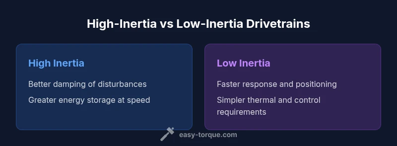
| Feature | High-inertia drivetrain | Low-inertia drivetrain |
|---|---|---|
| Effect on angular acceleration | Lower acceleration for high inertia | Faster acceleration for low inertia |
| Energy storage at a given speed | Greater energy storage for high inertia | Lower energy storage for low inertia |
| Control and damping needs | Easier to damp with higher inertia | Requires tighter control with low inertia |
| Best use-case | Heavy smoothing and load buffering | Fast response and precision control |
| Cost and mass considerations | Higher mass and potential cost | Lower mass may reduce inertia but demand advanced control |
Pros
- Better predictability with matched inertia and torque
- Smoother operation in pulsed-load environments
- Opportunities for energy buffering with high inertia
- Clear design guidance for balancing weight and performance
Drawbacks
- Higher mass and inertia can increase component wear and energy costs
- Low inertia demands more sophisticated control and fast actuation
- Inertia optimization may complicate packaging and cooling
Low inertia wins for responsiveness; high inertia wins for stability and energy buffering
For applications requiring quick, precise motion, a low-inertia design is typically superior. When smoothness, load buffering, or energy storage are priorities, a higher inertia approach is advantageous; the best choice depends on the performance envelope and control capabilities.
Your Questions Answered
What is the practical difference between torque and inertia?
Torque is the rotational force that changes angular velocity; inertia resists that change and stores kinetic energy. Together, they define how quickly and smoothly a system can accelerate or decelerate. In engineering practice, you size both to meet performance targets and avoid instability.
Torque is the force that makes things spin faster, while inertia resists that change. Balancing both gives you smooth, predictable motion.
How does moment of inertia affect acceleration?
Angular acceleration equals torque divided by inertia. Higher inertia reduces acceleration for a given torque; lower inertia allows faster acceleration. This relation underpins motor sizing, gearing choices, and control strategies.
More inertia means slower acceleration for the same torque, so you match inertia to the motor you have.
Can inertia be reduced without sacrificing strength?
Yes, through smarter design: lightweight materials, mass distributed closer to the axis, and modular components. Ensure structural integrity and load capacity are preserved by validating performance under worst-case conditions.
Yes—you can reduce inertia with lighter parts and smarter layouts while keeping strength.
Why is inertia important in flywheels and clutch design?
Flywheels store energy and smooth torque delivery; inertia helps damp fluctuations but requires proper sizing to avoid sluggish response. Clutches interact with inertia by controlling the rate of acceleration and deceleration.
Inertia in flywheels smooths power; in clutches it controls how quickly things start and stop.
How do you calculate torque if you know inertia and angular acceleration?
Use tau = I * alpha. If you know angular acceleration and the system's moment of inertia, multiply them to estimate the required torque. Include losses and safety factors in real designs.
Torque equals inertia times angular acceleration.
What is the best way to balance torque and inertia in a DIY project?
Model the system, estimate inertia, select a motor with adequate torque, and ensure the control system can handle the expected acceleration without overshoot. Iterate: test, measure, and adjust gearing and damping.
Model, test, and tune; keep it simple and adjust as you go.
Top Takeaways
- Match inertia to torque capacity for your load
- Prefer low inertia for fast, precise motion
- Choose high inertia to dampen disturbances and store energy
- Always consider control bandwidth and gear reflections