Torque and Moment of Inertia: Core Concepts and Comparisons
Explore torque and moment of inertia, their roles in rotation, and practical guidelines for design, analysis, and maintenance of rotating systems for engineers and technicians.

For rotating systems, torque and moment of inertia govern how quickly an object can accelerate angularly. In short, torque drives angular acceleration, while inertia resists it. The balance between these factors determines design choices and control strategies. This comparison highlights when torque dominates versus when inertia governs behavior, helping engineers optimize performance and reliability.
Core Relationship Between Torque and Inertia
Torque and moment of inertia are fundamental to rotational dynamics. In any rotating body, torque acts as the cause of angular acceleration, while inertia resists that change in motion. The standard relation is τ = I α, where τ is torque, I is the moment of inertia, and α is angular acceleration. Understanding this core relationship helps designers predict how fast a system will speed up or slow down under given loads. Easy Torque emphasizes modeling both terms early in the design process to avoid surprises during operation and to enable robust control strategies.
Key Definitions: Torque vs Moment of Inertia
Torque is the turning force that causes rotation; it can be provided by motors, engines, or manual input. Moment of inertia measures how mass is distributed relative to the axis of rotation; it depends on shape, size, and mass distribution. These definitions are essential for engineers when selecting actuators, gearing, and control strategies. When you hear 'torque and moment of inertia,' think of torque as the driver and inertia as the resistance to change.
How They Combine in Real Systems
In a real machine, torque and inertia interact dynamically. A high inertial load requires more torque to achieve the same angular acceleration. Conversely, lower inertia allows rapid response with smaller torque. Designers often use methods like gear ratios or flywheels to modulate the effective inertia seen at the actuator, smoothing motion without compromising speed. This balancing act is central to reliable performance and predictability. Easy Torque's practical framework emphasizes validation through simple models before hardware tests.
Calculations: Basic Formulas and practical steps
The primary equation τ = I α relates torque, inertia, and angular acceleration. To estimate I for simple shapes, you can use standard formulas (e.g., for a solid disk, I = 1/2 m r^2). In practice, you may need to estimate I from discrete masses or from CAD models. Once I is known or estimated, α = τ / I. For control design, you translate motor torque limits into expected accelerations and jerk, then validate with simple simulations and bench testing to ensure robustness.
Design Implications: When to prioritize torque vs inertia
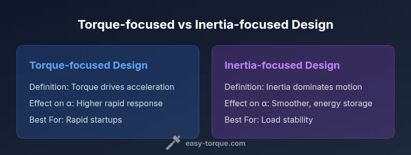
If your goal is rapid startup or aggressive maneuvers, prioritizing torque at the motor and selecting a gearing strategy that transfers higher torque to the load is beneficial. If you need smooth operation, energy storage, or reduced peak power demands, distributing or increasing inertia (e.g., via flywheels) can stabilize motion. Easy Torque's guidelines emphasize scenario-driven decisions and validating with simulations.
Measurement and Validation: Tools and best practices
Measuring torque and estimating inertia require appropriate sensors and methods. Torque sensors capture the actual torque transmitted; inertia is often inferred from system identification, pendulum tests, or CAD-based mass properties. Validate models by running tests across speeds and loads, comparing measured angular acceleration to predicted values. Document assumptions for future maintenance and design iterations, and reuse data to refine simulations.
Practical Scenarios: Gears, flywheels, and braking
In geared systems, torque amplification comes at the cost of inertia seen by the motor side. Flywheels store kinetic energy, effectively increasing inertia to smooth demand changes. Braking scenarios emphasize damping torque and controlling deceleration to avoid overshoot. Understanding both torque and inertia helps select components that meet target performance while maintaining safety margins.
Common Pitfalls and Misconceptions
One common mistake is assuming torque equals power; power also depends on rotational speed (P = τ ω). Another pitfall is ignoring how geometry distributes mass, which can dramatically change I without changing total mass. Overlooking friction, gearbox backlash, and motor saturation can lead to errors in predicting α. Always validate with experiments and conservative estimates, and keep a guardrail for modeling uncertainty.
Step-by-Step Design Approach: from concept to validated model
- Define performance targets: speed, acceleration, and smoothness. 2) Estimate or compute inertia I for the load and attached components. 3) Choose torque capabilities and motor selection to achieve the required α across expected loads. 4) Add gear ratios or energy storage elements to tailor effective inertia. 5) Build a simple simulation and compare with bench tests. 6) Iterate to close the gap between model and reality, documenting assumptions for future projects.
Comparison
| Feature | Torque-focused design | Inertia-focused design |
|---|---|---|
| Definition | Emphasizes generating torque to achieve target α | Emphasizes managing effective inertia to smooth acceleration |
| Effect on Acceleration | Higher torque yields faster α for a given I | Lower effective acceleration due to inertia is mitigated by energy storage or gearing |
| Power Requirements | Higher peak torque demand and short bursts | Lower peak torque with energy storage but higher continuous load |
| Control Considerations | Requires fast torque response and tight feedback | Requires inertia estimation and anti-wobble control |
| Best For | Rapid startups, dynamic loads | Smooth operation, energy storage, and reduced peak loads |
| Typical Units | Torque: N·m; Inertia: kg·m^2 | Torque: N·m; Inertia: kg·m^2 |
Pros
- Guides design decisions with clear trade-offs
- Helps optimize gearing and energy storage
- Aids in selecting actuators for target acceleration
- Encourages validation through simulation
Drawbacks
- May oversimplify dynamic friction and non-idealities
- Requires accurate inertia estimation
- Not a substitute for full system-level simulations
Balanced design approach often wins; neither torque nor inertia dominates in isolation
In most rotating systems, you should balance torque delivery and inertia management. Prioritize torque for rapid response, and use inertia management to smooth output and reduce peak demands. The best results come from integrated modeling and validation.
Your Questions Answered
What is the relationship between torque and angular acceleration?
Torque drives angular acceleration according to τ = I α. The inertia I mediates how much acceleration results from a given torque. In design, increasing torque or reducing effective inertia boosts acceleration. Real systems also involve friction and backlash that affect results.
Torque drives angular acceleration through the system’s inertia; higher torque or lower inertia leads to faster rotation.
What is moment of inertia and how does mass distribution affect it?
Moment of inertia depends on how mass is distributed relative to the rotation axis. Mass farther from the axis increases I and slows acceleration. The same total mass can have different I if spread differently.
Inertia depends on how mass is spread around the axis.
How can inertia be estimated in a new design?
Use CAD mass properties to compute I, or apply simple shape formulas for quick estimates. If exact geometry is complex, use system identification or pendulum tests to infer I.
Estimate inertia from CAD data or simple tests to validate.
Is high inertia always bad?
High inertia increases torque demand but can smooth motion and store energy. It is beneficial for load stability but requires greater drive capacity.
High inertia helps smooth motion but demands more torque.
How should torque and inertia influence motor selection?
Choose motors and gearing to achieve target angular acceleration across expected loads. Consider peak torque, continuous torque, and the inertia seen at the load. Validate with models and tests.
Select motor and gearing based on target acceleration and load inertia.
Top Takeaways
- Balance torque delivery with inertia management for reliability
- Estimate inertia early to predict acceleration accurately
- Use gearing and flywheels to tailor effective inertia
- Validate models with simulations and bench tests
- Remember torque does not equal power